Fundamentals of Sound
MODULE 2B: BASIC ACOUSTICS (continued)
Resonance - Sound Propagation - Musical Instruments


Resonance (Resonators / Filters)
Sound Propagation
   Reflection - Diffusion - Reverberation - Absorption
   Diffraction - Refraction - The Doppler effect
Musical Instruments as Sound-Wave Generators and Transmitters


Resonance


In science, the term resonance describes the phenomenon of maximum energy transfer among two or more oscillating systems, occurring as the vibration frequency of the energy-supplying system (driving system) approaches the natural frequency (resonant frequency) of the receiving system.

Natural frequency: The frequency with which a system would vibrate if energy was supplied to it and then it was left on its own.
   Think of pushing a swing, plucking a string, or striking a drum and then letting them vibrate on their own without further intervention.

Matching of the driving and natural frequencies maximizes resonance build-up of energy in the receiving system (see this interactive applet - requires the Java plug-in).
Energy build-up from resonance can have extreme outcomes (e.g.   Tacoma Narrows Bridge collapse;    voice breaking glass).

When excited/driven, the sound producing parts, or generators, of musical instruments (e.g. strings, drumheads, reeds, metal bars) vibrate at their resonant/natural frequencies.
Resonators of musical instruments (e.g. body and air cavity of a guitar or a violin; air column/cone and material of a clarinet/saxophone/trumpet/organ pipes/vibraphone tubes/etc.) function as amplifiers, enhancing frequencies that match or are close to the range of natural frequency(ies) of a given instrument's generator(s). 


Natural (resonant) frequencies of physical bodies depend on their physical characteristics such as size, shape, stiffness/tension, material/mass/density, etc.

General guidelines to determine natural frequencies of vibrating bodies:

  • the longer a string (e.g. on a guitar) or an air column (e.g. inside a trombone), the lower its natural frequency;
       in general, frequency is inversely proportional to length (for wooden/metal bars, frequency is inversely proportional to the square of the length)
     
  • the more massive a string or a drum head, or the larger the air volume inside a space/instrument, the lower its natural frequency;
       in general, frequency is inversely proportional to mass
     
  • the higher the tension on a string or a drum head, or the stiffer the vibrating material (e.g. xylophone/vibraphone bars), the higher its natural frequency;
       in general, frequency is directly proportional to the square root of tension/stiffness
     
  • the more symmetrical a shape and the less discontinuities, the simpler the resonance (i.e. the less frequency components in the spectrum of the resonance) and the more harmonic its spectrum (i.e. its frequencies are equal or close-to-equal to integer multiples of the lowest natural frequency);
    For example
    a) a perfect cylinder whose air cavity is excited just by an air stream (flute; pan flutes, etc.) will produce a sound signal with a harmonic spectrum, dominated by its fundamental
    b) a struck cymbal will produce a sound signal with an inharmonic spectrum, dominated by higher frequency inharmonic components (overtones).

Most musical instruments incorporate resonators with shapes, materials, and construction that result in a range of 'natural' frequencies so that they may respond to multiple frequency components of a single note and to more than one note.
Musical resonators are, therefore, broadly tuned. That is, they are shaped and constructed in ways that support resonance of (or amplification at) a wide/broad range of frequencies rather than a single frequency.


Conductive (forced) Resonance

 The resonator (e.g. guitar body) starts vibrating because it is in physical contact (e.g. via the bridge) with a vibrating body (e.g. strings), which "forces" the resonator to replicate the oscillations
[ animation example of conductive resonance, showing exaggerated modal vibrations of a guitar body in response to string vibrations ]

Sympathetic (free) Resonance

The resonator (e.g. marimba's resonating tubes) starts vibrating in response to wave energy (e.g. from the vibration of struck wooden bars) reaching it via the air
[ video example of sympathetic resonance ]

 
An intermediate condition between
   a) full contact (direct, strong coupling; conductive resonance) and
   b) no contact (air coupling; sympathetic resonance)
is weak coupling/conductive resonance (e.g. multiple pendulums with their masses connected by springs).
Weak coupling can promote energy build-up through synchronization among multiple oscillators [ metronome synchronization video example - optional details here ].

The figures, below, show the response (y axis) of a resonator with natural frequency f0 when driven at various frequencies (x axis) and at different degrees of damping/friction/resistance/drain [ figure below-right:    f0 =440Hz;   blue: low damping;  green: medium damping;  red: high damping ].


Short video on the relationship between driver frequency and resonator response.


Key Observations on Resonator Response
 
Resonator response:

_ is greatest when driven at or near its natural frequency
 
_ is greater when driven at frequencies that are below versus above natural frequency;

for driving frequencies below natural frequency, resonator response matches, at a minimum, the driver's amplitude
 
resonator response drops quicker as driving frequency extends above versus below natural frequency, dropping to almost zero

_ level, sharpness, and "best" resonance frequency decrease as damping increases
 
In general, the broader the frequency response the lower the maximum response level (why?)


Resonance and Filters

 
Resonators are analogous to filters.
Both, resonators and filters selectively amplify and/or attenuate different frequencies based on their (physical/electronic/digital) characteristics. The figures, below, illustrate the four most common types of idealized filters.
 
                                               
Resonator/Filter Q factor, Bandwidth & Damping;

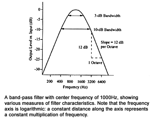
Q factor (Quality factor or 'sharpness') of a filter/resonator is a measure of its frequency response width.
Q = [Resonant Frequency]  /  [Response Frequency Bandwidth]  [ Frequency Bandwidth: upper freq minus lower freq within a frequency range ]

_The heavier the damping, the broader the filter response (i.e. the wider the filter shape) and the lower its Q factor.
_The lighter the damping, the narrower the filter response (i.e. the narrower the filter shape) and the higher its Q factor.


_ 3dB Response Bandwidth:
    frequency bandwidth where response drops by 3dB
    Note: for electronic filters, a 3dB drop corresponds to a
    50% drop in intensity (or power) but an ~30% drop in
    Voltage [ optional explanation ]

_ 10dB Response Bandwidth:<    frequency bandwidth where response drops by 10dB

_ >_ Filter slope:
    response level change over one octave
    [ figure to the right

Why, do you think, 3dB and 10dB are chosen as markers for a filter's shape?


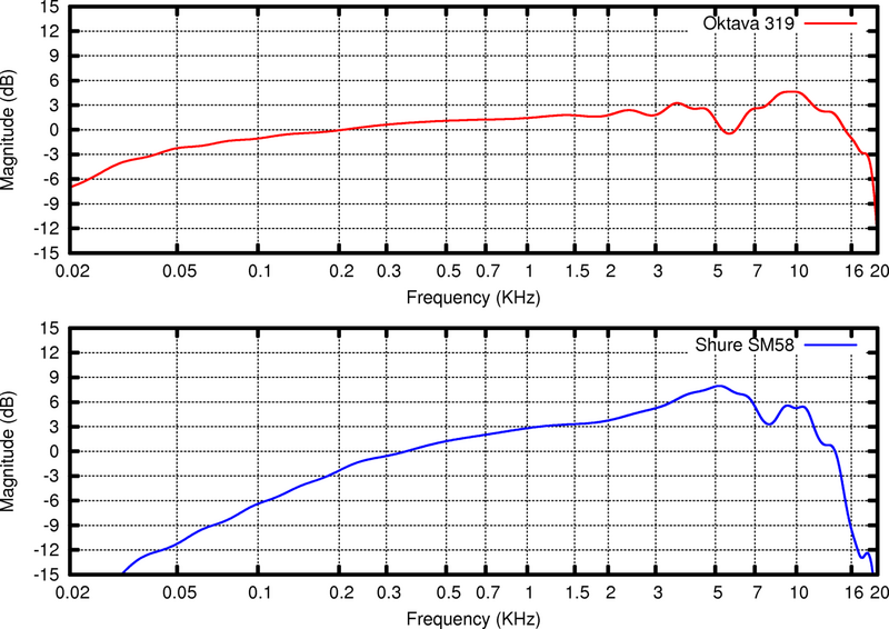
The figures, below, are spectral envelopes, illustrating the frequency response of two popular vocal microphones and are aptly named frequency response curves. They plot level over frequency but only include the spectral envelope line (i.e. the line connecting the tips of each implied, underlying spectral component).

Frequency Response Curves show:

  • how each microphone resonates (mechanically, via its diaphragm, and electronically, via its circuit) in response to a sound wave and
  • how this response varies with frequency.

The frequency response of an ideal microphone would be a flat horizontal line, parallel to the frequency axis, broad enough to extend over the entire frequency range of human hearing (i.e. 20-20,000Hz), and crossing the level axis at (or near) 0. Such response is not practically feasible (why?). The better the microphone, the closer it approximates it.

Microphones closely approximating flat frequency response over the entire frequency range of human hearing:

  1. faithfully capture the sound waves originating from a source, without altering them by under/over emphasizing any frequencies, a feature that, incidentally, also reduces the likelihood of feedback ringing (why?) and
  2. support the broadest possible applications (e.g. can faithfully capture sources whose sound spectra occupy the extremes of the frequency range).


How microphones work (animations): outline - dynamic mics - condenser mics


Resonance of Stings, Air Columns, & Plates

 
Standing waves are a form of resonance and develop at the natural frequency(ies) of oscillating systems.

The harmonic spectral components, or harmonics, of the tones produced by standing waves on a string (below) correspond to wavelengths λ that relate directly to the length of the string L.
For each standing-wave pattern or mode of vibration, each loop corresponds to 1/2 wavelength. So, the 1st (fundamental), 2nd, and 3rd modes (and consequently, harmonics) have the following wavelengths λ with respect to string length L:

λ1=2/1L;    λ2=2/2L;    λ3=2/3L. Conversely,  L = 1/2λ1 = 2/2λ2 = 3/2λ3.

The two resources, to the right, illustrate the generation of sawtooth standing waves (i.e. modes of vibration) on strings, initiated through conductive (i.e. forced) resonance.

 
Analogously, the harmonic spectral components, or harmonics, of the tones produced by standing waves / modes of vibration within an air column (below) also correspond to wavelengths λ that relate directly to the length of the air column L. Again, for each standing wave pattern, each loop corresponds to 1/2 wavelength (idealized contexts/shapes).

Cylinder open at both ends (below left - flutes, pan flutes, some organ pipes, etc.):
   The 1st (fundamental), 2nd, 3rd, and 4th modes/harmonics have the following respective wavelengths:  λ1=2L;   λ2=1L;   λ3=2/3L λ4=1/2L
Cylinder closed at one end
(below middle - clarinet, several non western woodwinds, etc.):
   The 1st, 2nd, 3rd, and 4th modes/harmonics have the following respective wavelengths: λ1=4L;   λ2=--;   λ3=4/3L;   λ4=-- (only odd components)
Cone closed at one end (below right - oboe, saxophone, etc.):
   The 1st, 2nd, 3rd, and 4th modes/harmonics have the following respective wavelengths: λ1=2L;   λ2=1L;   λ3=2/3L λ4=1/2L


The full story is more complicated due to length and tension changes, as a string is excited, and due to "effective" air-column length changes, as a column's diameter and shape change.


For most practical purposes, and assuming equal length:

  • The lowest note produced by strings, conical instruments (e.g. saxophone), and cylindrical instruments open on both ends (e.g. flute) has similar wavelength & frequency across instruments.

  • The lowest note produced by cylindrical instruments of the same length, but which are closed on one end (e.g. clarinet), has wavelength & frequency corresponding to a note one octave lower. 


Resonances of metal plates (e.g. cymbals) produce signals with inharmonic spectra (i.e. with components whose frequencies are not integer multiples of the lowest frequency) and tones with no definite pitch.
The relationship between cymbal dimensions and wavelengths is quite complex but cymbal vibrations do follow specific vibration patterns, also referred to as modes of vibration (see here and below).


Helmholtz Resonators - Bass Reflex Loudspeakers

Helmholtz resonators (named after 19th century physicist and physician, Hermann von Helmholtz) are spherical or cylindrical containers with a short, narrow neck, open at one end. 
The air in the container acts like a spring and the air in the neck acts like a mass, vibrating because of the 'springiness' of the air inside.

   where
        f: resonance frequency
        c: speed of sound
        A: neck cross-section area
        l: neck length
        V: container volume


Consider a 'lump' of air at the neck of the bottle (shaded in the middle diagrams).

_ An air jet forces this lump of air a little way down the neck, compressing the air inside.
_ The increased pressure of the compressed air, inside, drives the 'lump' of air back out but, when it gets to its original position, its momentum moves it a small distance outside the neck.
_ This rarifies the air inside the body, which then sucks the 'lump' of air back in, and so on. 

A jet of air from your lips, for example, is capable of deflecting alternately into the bottle and outside, providing the power that keeps the oscillation going.
The frequency of the vibration is related to the speed of sound in air c, the length l and area A of the container neck, and the volume V of the container, as indicated in the equation, above.
In this "mass-spring"-like system:
_ longer necks ( l ) and larger containers (V) produce lower frequencies
_ wider necks (A) produce higher frequencies
.

For example, Helmholtz resonance is applied to narrow-band sound absorption (see further below) and to low-frequency amplification via the inclusion of a bass reflex enclosure (or tuned port) to a loudspeaker. Bass reflex enclosures improve a loudspeaker's low frequency efficiency and range of response.

They consist of:

  • an appropriately shaped/sized air cavity inside the loudspeaker enclosure, paired with
  • an opening/tube connecting the inside of the speaker box with the outside, whose shape and position have been carefully adjusted to support resonances at the desired frequency range.

The air volume of the enclosure acts as the air in the body of a Helmholtz resonator. The supported resonant frequency range is determined by the geometry of the enclosure/tube/opening system, deliberately chosen to smoothly extend the frequency range of the speaker system below its original low cutoff frequency.
In addition, the existence of the port greatly reduces the air pressure variation between the inside and the outside of the speaker box, facilitating transmission of wave energy from the inside of the instrument to the outside (see reflection / transmission, below). More details here.

How loudspeakers work (animations): outline - component breakdown - cone & surround


SOUND PROPAGATION

Reflection - Transmission - Diffusion/Reverberation - Absorption


When a sound wave meets a boundary, whether within a medium or separating two media (1 & 2), some of the wave energy may be

_ Reflected (bounce) back, possibly generating standing waves, echoes, or reverberation.
_ Transmitted
(pass through or around the boundary).

The energy that will pass through/around the boundary may be
   _ absorbed
(soaked up by the boundary),
   _ diffracted
(bent around the boundary),
   _ refracted
(bent inside medium 2), and/or simply
   _ transmitted
into medium 2.

Reflection

Acoustics borrows the basic law of reflection from optics: The angle of reflection will be equal to the angle of incidence, around the reflecting surface's normal*.
[ *normal: in 3D space, the normal to a surface at point P is a vector perpendicular to the tangent plane of the surface at P - in reflection, the incident, normal, and reflected vectors are on the same plane ]


The balance between reflected and transmitted energy at a boundary is determined by the impedance (resistance) relationship of the areas either side of the boundary:

The larger the impedance mismatch and the larger the angle of incidence the greater the reflected energy.

Practically all musical instruments rely on reflection to build up standing waves and produce sound.
They achieve this by involving structures with appropriately placed boundaries and impedance mismatches.

If

z1: impedance of the medium from where the sound wave originates
z2: impedance of the medium to which the sound wave moves

then

If z1 = z2 (not displayed):  no reflection / total transmission.
If z2 < z1 (below, top-right):  reflected & incident waves are in phase.
If z2 > z1 (below, bottom-right): reflected & incident waves are 1800 out of phase.
If z2 <<< z1 (below, top-left) or z2 >>> z1 (below, bottom-left):  total reflection / no transmission 


OPTIONAL: More specifically:
If     I0: Incident Intensity;   Ir: Reflected intensity;  &  It: Transmitted intensity;    then 
    Proportion of Reflected Intensity   = Ir / I0 = [(z1 / z2) -1 / (z1 / z2) + 1]2   =   [(z2-z1) / (z2+z1)]2  
    Proportion of Transmitted Intensity = It / I0 = 1 - Ir / II0 = 1 -  [(z2-z1) / (z2+z1)]2  = 4z2z1 / (z2+z1)2 
[ for a detailed derivation see here - remember that intensity is proportional to the square of pressure ]


Examples of reflection - dependence on impedance
(from the University of Saskatchewan, Department of Engineering Physics)

Total reflection at a free end (Z2 = 0)
 

Z1/Z2 = 2, (i.e. the second medium is lighter)
(reflected plus transmitted energy = original energy)
 

Total reflection at a fixed end (Z2 = infinity)

Z1/Z2 = 0.5 (i.e. the second medium is heavier)
The reflected wave reverses its phase
(reflected plus transmitted energy = original energy)


Diffusion / Reverberation

Successive, partial, uncorrelated  reflections [ i.e. reflections that are not coherent / not in the same or symmetrical direction(s) ] from the surfaces in an enclosure, such as the uneven complex-shaped walls of an auditorium, result in the scattering of the sound waves and diffusion of sonic energy (see below). Repeated, diffused reflections are perceived as reverberation
 
Reverberation is a desirable property of auditoriums to the extent that it
    a)
helps overcome the inverse square law drop-off of sound intensity in the enclosure;
    b) reduces overall and frequency-specific level discontinuities within an enclosure; and
    c)
contributes to the sonic character of a musical style.


Reverberation time is defined as the time it takes for the sound resulting from multiple diffuse reflections to lose 60dB of its original level.

Explore qualitatively the top level of these two resources: Reverberation & Reverberation Time (Hyperphysics, Department of Physics and Astronomy, Georgia State University). You are not expected to follow the links within them or do any calculations. More on reverberation later in the course.
 

Absorption describes the loss of energy as a wave propagates through a medium and/or strikes a boundary (see to the left).

For example, sound can be absorbed through

a) friction as a sound wave propagates in air,
b) trapping as a sound wave strikes a pliable and/or porous boundary,
c) thermal loss of energy, or
d) decoupling and interference when encountering layered boundaries.

The degree to which a medium absorbs sound is expressed by its coefficient of absorption, a.
Absorption coefficients range from 0 to 1, are frequency-dependent, and are related to the medium's material and structure.

_ Brief qualitative outline of absorption and a table of absorption coefficients of common materials.
_ Additional table with absorption coefficients.

  • Velocity absorbers (porous materials, such as foam or fiberglass) absorb sound via frictional air movement, are broadly tuned, and work best on mid/high frequencies, which develop high particle motion velocity.
  • Pressure absorbers (tuned membranes and "traps," like Helmholtz resonators) absorb sound via interference and diffusion, are narrowly tuned, and work best on low frequencies, which develop high sound pressure levels, particularly near reflective boundaries.
    [ optional details on tuned membrane absorbers ]
  • Hybrid absorbers (modified Helmholtz absorbers and drapes of varied mass/densities/spacing in multilayered arrangements) combine the characteristics of velocity and pressure absorbers to achieve substantial absorption over a broad frequency range. However, they are very costly and require installation space that is usually unavailable or the development of new types of material.
    [ optional details: on layered Helmholtz absorbers here & here;  on layered drape absorbers here & here ]


Diffraction - Refraction - The Doppler Effect
[ sound-wave transmission special cases ]


Diffraction

Diffraction describes the ability of sound waves to bend around obstacles and through openings whose smallest dimension is smaller than the wavelength(s) of the sound waves.
Diffraction phenomena largely determine:
   a) the radiation patterns of (i.e. the ways the sound spreads out of) sound sources, such as musical instruments and loudspeakers;
   b) the pick-up patterns of (i.e. the ways the sound comes into) sound receivers, such as microphones and the human ear; and
   c) the movement of sonic energy through spaces that include obstacles/openings. 

In general:
Low frequencies diffract more than high frequencies
, because it is more likely for obstacles/openings commonly encountered in everyday life to be smaller than the wavelength (λ) of low vs. high frequencies. 

More specifically:
Diffracted energy begins at wavelengths >≈ half the size of the opening /obstacle in question [ or for obstacles <≈ twice the wavelength(s) in question ] &
It becomes almost total at wavelengths four times the opening/obstacle [ or for obstacles 1/4th of the wavelength(s) in question ].
For example, since the wavelengths of low frequencies are usually larger than the loudspeakers (e.g. subwoofers) reproducing them, they radiate away from the loudspeakers spherically. [ could we somehow restrict their radiation pattern and make subwoofers directional? ]

Diffraction behavior through openings and around obstacles:
_ is similar in that, the smaller the opening/obstacle, the higher the proportion of diffracted (i.e. bent) energy.
_ is different in that, the smaller the opening, the smaller the proportion of total energy that will be transmitted through it.
Play around with this simulation to explore the impact of opening size to diffraction (select the "slits" option and experiment with the frequency and slit-width faders).
 

Diffraction behavior examples at different wavelengths , assuming c = 345m/s @ 210C:

a) f = 66Hz (e.g. fundamental freq. of ~ a C2 note played on a bass guitar) =>
   
 => T = 1/66 secs/cycle;          ---       λ = c*T = 345*1/66 => λ=5.23m/cycle  
    [ alternatively, λ = c/f = 345/66 => λ=5.23m/cycle ]
    At this frequency:
    _ diffracted energy begins to be appreciable for openings/obstacles <≈10.46m and becomes almost total for openings/obstacles  <≈1.31m.
    _ sonic energy blockage begins to be appreciable for obstacles >≈10.46m and becomes almost total for obstacles  >≈20.92m
 
b) f = 528Hz (e.g. fundamental freq. of ~ a C5 note played on a flute) =>
    => T = 1/528 secs/cycle;        ---        λ = c*T = 345*1/528 => λ=0.65m/cycle
    [ alternatively, λ = c/f = 345/528 => λ=0.65m/cycle ]
    At this frequency:
    _ diffracted energy begins to be appreciable for openings/obstacles <≈1.30m and becomes almost total for openings/obstacles  <≈0.16m.
    _ sonic energy blockage begins to be appreciable for obstacles >≈1.30m and becomes almost total for obstacles  >≈2.6m

Most sounds correspond to complex signals and have spectra with more than one frequency component.
Consequently, for a given set of openings/obstacles, portions of the sound's spectrum may be diffracted and portions may not, resulting in a perceived sound quality that depends on the position of a listener relative to the "sound-source - obstacle/opening" system in question. More during the discussion on timbre.
 

Illustrations of diffraction - dependence on frequency
[ from Hyperphysics, GSU ]


Refraction

Refraction describes a change in the propagation direction of sound waves as they move across two media where sound waves travel at different longitudinal velocities [ see Refraction at Hyperphysics, GSU ]

Optional: According to Snell's refraction law, sinθ1 / sinθ2 = v1 / v2

Reflection and Refraction laws are derived from Fermat's Least Time principle.
Refraction and Diffraction are both theoretically explained by combining the Huygens-Fresnel Wavefront principle and Bernoulli's Linear Superposition principle.

In the figure to the right: v2 < v1 => the sound waves refract/bend towards the "normal" (: dotted line, perpendicular to the boundary).
The sound waves would bend in the opposite direction (away from the "normal") if v2 > v1

Example

The speed of sound in air depends on temperature and on wind speed and direction. Therefore, sound waves may be refracted as they cross layers of air that are at different temperatures (e.g. as they rise above the ground) and/or subject to different wind directions and speeds (see the figures, further below, for illustrations of the refraction effects of temperature and wind differentials).
Consequently, basing orientation of an open air theater relative to prevailing winds in the area and to air-temperature-differential considerations is crucial to efficient sound transmission to the audience and the minimization of sound disturbance to the surrounding areas.


Play around with this interactive applet exploring the phenomenon of refraction.


The Doppler effect

The Doppler effect [ named after the 19th century Austrian physicist, Christian A. Doppler, who first quantified it ] describes received frequency as a function of the relative motion of source and receiver. It has found applications in optics, astronomy, medicine, audio, and much more [ optional details ].

For example, when a sound source moves relative to a listener, the emitted frequency will appear higher (as the source approaches) or lower (as the source recedes) than the emitted frequency, because wave fronts are compressed in-front of a moving source and are spread apart behind it.

_ Hyperphysics resource on the Doppler effect - approach any equations qualitatively [ alternative, multimedia-rich explanation ]

A popular musical application of the Doppler effect is in the Leslie Organ Loudspeaker, producing a distinct frequency modulation (vibrato) effect.

If the source moves faster than sound, wave-fronts will pile up and add behind the source, resulting in the "sonic boom" effect experienced, for example, when a supersonic airplane breaks through this wall of compressed air. Notice how you can barely hear the plane approaching [ more detailed video ].


Illustrations of the Doppler effect - dependence on source speed
(from the University of Saskatchewan, Department of Engineering Physics)


                      Source velocity = 1/2 * Sound velocity


Source velocity = 2 * Sound velocity                         


Resources

Explore these interactive tools (first three sections):
   _ Oscillations and Waves: Ripple Tank
   _ Acoustics: (all available)
   _ Signal Processing: Fourier Series

Additional Physics Simulations

Bookmark and return to the following online resources to expand your understanding on any specific topic.
Deep links on specific concepts within these resources are dispersed throughout our course site:
   _ Hyperphysics: Physics and Psychophysics of Sound and Hearing
      (Department of Physics & Astronomy, Georgia State University, Atlanta, USA)
   _ Music Acoustics
      (University of New South Whales, Sydney, Australia)
   _ Tutorials and Interactive Labs on Sound, Waves, & Music
      (Online Physics Classroom)
   _ Fundamentals of Musical Acoustics Video Playlist


Musical Instruments as Sound Generators and Transmitters


HISTORICAL APPROACH

 
The most common (but highly inconsistent) lay-language classification of musical instruments splits them into three categories:

_ Percussion
_ Winds
(brass & woodwind)
_ Strings

The standard classification system of musical instruments originates in the work of Mahillon, a curator of musical instruments at the Brussels Music Conservatory (early 1800s).
Mahillon's system was modified and expanded by Hornbostel and Sachs [ optional: the Hornbostel-Sacks system ] to encompass instruments from cultures outside the Western musical tradition.

The system includes 5 principal categories  --mainly (but not always) based on the material that is excited first when an instrument is played-- and several subcategory levels, adding up to over 300 basic groupings:
 

Idiophones produce sound mainly through vibrations of their body - through 3-dimentional standing waves on the entire instrument (cymbals, xylophone, cowbell, etc.)
Membranophones produce sound mainly through vibrations of a stretched membrane - through 2-dimensional standing waves on membranes (all drums, kazoos, etc.)
Chordophones produce sound mainly through vibrations of one or more stretched strings - through 1-dimentional standing waves on strings (guitar, harp, piano, violin, etc.)
Aerophones produce sound mainly through vibrations of air within a volume outlined by the instrument - through 3-dimentional standing waves on bounded air volume(s) (saxophone, oboe, trumpet, organ, etc.)
Electrophones produce sound mainly through vibrations/oscillations of electrical voltage/current (synthesizers, theremin (explanation), etc.)

 
ACOUSTICS APPROACH


Within the context of acoustics, musical instruments are examined systematically in terms of:

  • their physical properties
  • the way energy is supplied, modified, and radiated, and
  • the resulting sonic perceptions
    [ outline in Hajda, J.M. (2009). Psychoacoustics and Organology. Journal of the Acoustical Society of America, 126: 2236 ]

This course examines musical instruments  as  driver - generator - resonator  systems  that incorporate some sort of:

  • coupling, facilitating energy transfer
       a) from the outside to the inside of the instrument (e.g. various mouthpieces)
       b) within the instrument (e.g. various bridges) and
       c) from the instrument to the surrounding air (e.g. various surfaces or openings/bells),
    and with different types of

  • articulation, controlling how driver vibrations are
       a) initiated (e.g. by striking, blowing, plucking),
       b) "stopped" (i.e. how they change pitch along a pitch scale),
       c) maintained (e.g. by bowing, blowing), and
       d) end (e.g. with/without performer intervention). 

Voice acoustics has adopted a slightly different terminology for the stages of this analytical approach: actuator (driver) - vibrator (generator) - resonator - articulator(s)
Beyond the terminology differences in the first two stages, the key difference is that voice production articulation occurs at the end of the sound production process and also facilitates the coupling of energy out the "instrument" and into the surrounding air. For most other instruments, articulation can occur at any of the system's stages.


The heart of any musical instrument is its sound generator.

The generator is the part of the instrument that, when excited by a driving force, will be the first to vibrate. It initiates the sound waves that travel through the instrument and out to the surrounding air, eventually reaching our ears or a microphone.
Examples of generators include:
strings (violin, piano,...);     reeds (clarinet, sax,...);     air (flutes, organ flue pipes,...);     lips (trumpet, trombone, bugle,...);
skins/membranes (various drums,...);     metal plates/bars (cymbals, gongs, vibraphone,…);     vocal folds (voice). 
The vibration characteristics of a generator outline the frequency and spectral ranges of the sounds produced.

_ Some generators are variable. For example:
Strings can be "stopped" (e.g. by pressing the string over a fret/neck), and the amount and location of pressure applied on reeds can be modified (e.g. by the way the player's lips interact with the saxophone reed), changing their physical and resonant characteristics, modifying the pitch and/or timbre produced.
 
_ Some generators are fixed. For example:
Instruments with fixed-length strings, such as pianos and harps [ exceptions: piano - harp ], or various percussion [ exceptions: tabla - tom ].

 
The driver that excites (sets into vibration) a generator can articulate (apply) a driving force:

  • in various ways: e.g. instantaneous (plucking, striking, etc.) or continuous (bowing, blowing, etc.).

    • for instantaneous articulation: driving force can be applied for various contact durations.
      E.g.
      plucking a string with the fingertips vs. a plectrum; striking a drum with a felt-tip vs. a wooden-tip mallet (i.e. longer vs. shorter contact).
      Note: The shorter the contact time between driver and generator and the faster the rate of energy supply:
              a) the more complex and important (perceptually) the attack portion of a signal's envelope to the resulting sound and
              b) the richer in high frequency components the resulting spectrum.
       

    • for continuous articulation: driving force can be applied with various degrees of modulation. For example:
      _
      vibrato (narrow frequency/pitch modulation or fast trills);
      _ tremolo (narrow amplitude/loudness modulation or fast repetitions of the same note);
      _ portamento (continuous slide up/down in frequency/pitch);
      _ glissando (discrete move up/down in frequency/pitch).
      Note: The more time-variant a signal the higher its salience in the presence of other signals (i.e. it can easier cut through other simultaneous signals).
       

  • at various locations on the generator: e.g. in the middle (i.e. away from any support); towards the edges (i.e. near a support).
    Note: The closer a driving force is applied to the middle of a generator (such as a string, a membrane, or a bar) the richer in low frequency components the resulting spectrum.

In general:
   _the amount of applied driving force is linked to the dynamic range of the sounds produced
   _the manner in which the driving force is applied is linked to the signal and spectral envelopes of the sounds produced.

 
A generator is coupled to (connected to / placed near), and therefore amplified, sustained, and spectrally “shaped” by some sort of resonating system

Resonating systems contribute to a musical instrument's frequency response*.
[ *Frequency Response: the degree to which energy provided by the generator is distributed and is amplified/reduced by the instrument's resonating system, within a frequency range of interest ].

Examples of resonators:
   _ soundboards [ e.g. piano; most acoustic string instruments;...]
   _ air cavities [ e.g. lutes; violins; drums; thumb piano (e.g. mbira/kalimba);...]
   _ air columns [ e.g. horns; pipes; tubes;...]
   _ vocal tract [ e.g. voice; flute;... ]; mouth cavity [ e.g. jew’s-harp; harmonica;...)
   _ membranes/plates [ resonant drum heads/plates;...]   -   etc.. 

The frequency response characteristics of a resonator influence the produced sound and depend on resonator size, shape, material, and construction. 
The resonating systems of musical instruments are preferably broadly (rather than sharply) tuned. That is, they preferably have an evenly-distributed frequency response, over a broad range of frequencies. In aerophones with variable resonators, air columns can be stopped (e.g. by pushing a trumpet valve or by gliding the outer slide tube of a trombone) to broaden the instrument's frequency response and pitch range.  

Musical instrument resonators are therefore designed so that they can more-or-less evenly respond at and amplify a wide range of frequencies, usually matching the fundamental frequency range of the instrument to which they are attached, as well as key upper harmonics.

 
Couplers (e.g. various types of bridges or, in the case of coupling through proximity, air) link generators and resonators, essentially modifying their degree of impedance matching/mismatching to control the balance between transmitted energy onto the resonator and reflected energy back to the generator .

The higher the degree of impedance matching between generator(s) and resonator(s) the higher the amount of energy transfer between them and the more efficient the coupler(s).

There is always some degree of energy feedback between generators and resonators that depends on coupling type and the note produced. Consequently, generators and resonators may alternate roles and sometimes do so in a periodic/regular manner.
The degree of such feedback and the nature of its periodicity determine, to an extend, the balance between an instrument’s radiation efficiency (see below) and decay time (i.e. how long it takes for the vibrations of the generator/resonator to die out after energy supply has stopped). 

The difference, for example, between the decay times of a hammer dulcimer string and a classical guitar or a piano string reflects, in part, the different degree and periodicity of feedback between their respective generators and resonators, which depends on coupling (i.e. bridges).

Note: For several idiophones (e.g. cymbals), generators and resonators coincide (e.g. metal plate). In such cases, articulation fulfills the function of coupling "in" (i.e. linking between generator and resonator).

An instrument’s coupling to the atmosphere (i.e. the way sound waves are transferred from the instrument to the surrounding air; e.g. via the bell on a horn) influences the spectral characteristics of the sound leaving the instrument, as well as its radiation pattern.

Radiation pattern: Term describing the way energy radiated from a sound source spreads away from it. Generally speaking, high frequencies are more directional (they follow a narrower path) than low frequencies, which spread more or less spherically (remember the discussions on the inverse-square law and on diffraction).

Radiation efficiency: Term describing the ratio of acoustic pressure just outside the end of an instrument to that just inside. 
Radiation efficiency varies according to instrument construction and the note being produced and is ultimately a function of the impedance difference between the inside and the outside of an instrument, which is modified by the coupler "out." In general, high frequencies radiate more efficiently than low frequencies.

The radiation efficiency and radiation pattern of a musical instrument dictate the relationship between
   a) the position of a listener or microphone relative to the instrument and
   b) its perceived timbre.


Musical Instrument Resources
 

Standard online resources addressing multiple instruments include:
   • Music Instrument Guides; Yamaha
   • Instrumentology; Vienna Symphonic Library

   • Musical Instruments; Hyperphysics
   • Music Acoustics; University of South Wales
   • The Physics of Music and Musical Instruments by David R. Lapp; Tufts University


Voice
   • http://hyperphysics.phy-astr.gsu.edu/hbase/Music/voice.html  (outline)
   • http://newt.phys.unsw.edu.au/jw/voice.html  ("Introduction and overview" section up to the "Source-filter interactions" subsection)
   • https://voicefoundation.org/health-science/voice-disorders  (resource on voice production, health, & conservation)
   • The Acoustics of the Singing Voice  (seminal 1977 paper by pioneer in voice acoustics, J. Sundberg)
   • Research on the Singing Voice in Retrospect  (follow-up by J. Sundberg to his 1977 paper)
   • https://www.youtube.com/watch?v=ZLgAQTMgZ6g  (voice production acoustics - video)
   • https://muse.union.edu/griffiths-capstone  (Modeling the Human Vocal Tract - 2014 student project by S. Griffiths)
   • https://youtu.be/UkNDBQmEMSY  (advanced review of formants; includes a link to a voice synth, based on formant manipulation - video)
 

Guitar
   • http://hyperphysics.phy-astr.gsu.edu/hbase/Music/guita.html  (outline)
   • https://newt.phys.unsw.edu.au/music/guitar/  (focus on "Basics about sound ...", "Anatomy of an acoustic....", & "Acoustics and components")
   • https://youtu.be/gbP6h0dtcQw  (guitar acoustics - video)
   • https://youtu.be/lBAZepM5F_0  (electric guitar fundamentals - video)
 

Marimba
   • http://hyperphysics.phy-astr.gsu.edu/hbase/Music/xylo.html  (outline)
   • https://en.wikibooks.org/wiki/Acoustics/Basic_Acoustics_of_the_Marimba  (short analysis)
   • https://www.vsl.info/en/academy/percussion/marimba  (construction; sound production; etc.)
   • https://www.youtube.com/watch?v=pCnFE-lSta4  &  https://www.youtube.com/watch?v=Bsj-xx25dHYY  (building a marimba - videos)
   • https://www.youtube.com/watch?v=RaYvMwQd3cs  (composition for six marimbas by Steve Reich - video)
   • https://www.jstage.jst.go.jp/article/ast/22/3/22_3_177/_pdf  (acoustics of percussion instruments - T.D. Rosing, 2001)
 

Trombonee
   • http://hyperphysics.phy-astr.gsu.edu/hbase/Music/trombone.html  (outline - details available)
   • http://newt.phys.unsw.edu.au/jw/brassacoustics.html  (info on all brass instruments, including the trombone)
   • https://acousticstoday.org/wp-content/uploads/2016/12/Brass.pdf  (detailed outline of brass instrument acoustics)
   • https://www.youtube.com/watch?v=CoxnhjLMVBo  (lip vibrations in trombone embouchures in 3 parts - video)
 

Flute
   • http://hyperphysics.phy-astr.gsu.edu/hbase/Music/flute.html  (outline)
   • http://www.markshep.com/flute/Acoustics.html  (outline)
   • http://newt.phys.unsw.edu.au/music/flute/  (detailed discussion and resource database)
   • http://www.flutepage.de/deutsch/goodies/physik.php?englisch=true  (detailed discussion)
   • https://ccrma.stanford.edu/~pdelac/research/MyPublishedPapers/Thesis.pdf  (doctoral dissertation; P.dela Cuadra, 2005; - advanced)
 

Saxophone
   • http://hyperphysics.phy-astr.gsu.edu/hbase/Music/sax.html  (outline)
   • http://newt.phys.unsw.edu.au/jw/saxacoustics.html  (detailed discussion and resource database)
   • https://syos.co/en-us/blogs/news/tagged/acoustics  (inside the saxophone)
   • https://www.tutorhunt.com/resource/3462  (physics of saxophone)
   • https://www.youtube.com/watch?v=nMjCwPDbFfU  (saxophone quintet performance - 1st part of Vivaldi's "Spring"; "Four Seasons" - video)
 

Cymbal
   • https://sabian.com/cymbals-101/  (overview)
   • https://www.youtube.com/watch?v=F2rxNwYcsN8  ("how it's made" - video)
   • https://www.vsl.co.at/academy/percussion/cymbals & https://www.vsl.co.at/academy/percussion/suspended-cymbal  (outline)
   • https://www.soundonsound.com/techniques/analysing-metallic-percussion  (detailed outline - Sound on Sound magazine)
   • https://scholarship.rollins.edu/cgi/viewcontent.cgi?article=1020&context=stud_fac  (detailed exploration - cymbal vibration modes)
   • https://iopscience.iop.org/article/10.1088/1742-6596/744/1/012110/pdf  (detailed exploration - striking effects)
   • https://www.jstage.jst.go.jp/article/ast/22/3/22_3_177/_pdf  (acoustics of percussion instruments - T.D. Rosing, 2001)
 

Floor Tom
   • http://hyperphysics.phy-astr.gsu.edu/hbase/Music/cirmem.html  (circular membrane vibration modes)
   • https://www.vsl.co.at/academy/percussion/field-drum  (tenor/field drum - no snares)
   • http://www.bustedgear.com/faq_Drum_miking.html  (overview)
   • http://drumzone.com.au/how_a_drum_works_9.html  (general overview of a drum kit)
   • https://www.yamaha.com/en/musical_instrument_guide/drums  (extended overview of a drum kit)
   • https://www.soundonsound.com/techniques/physics-percussion  (detailed outline - Sound on Sound magazine)
   • https://www.jstage.jst.go.jp/article/ast/22/3/22_3_177/_pdf  (acoustics of percussion instruments - T.D. Rosing, 2001)


Loyola Marymount University - School of Film & Television